Fourth week 7/22/2019 - 7/27/2019 : (More) Improving Designs
On monday meeting at 4pm with Ron, Pr. Furman, Eric, Ethan and Jacques-Hariel we talked about the designs of the last week. We introduced Thomas (Jisup) who is an industrial design major and he talked with Pr. Furman about his participation in the projet and about the work done by the last industrial design majors.
We had another meeting at 6h30 with Daniel and he gave some ideas to simplify the switch of the 2 floors bogie (crank rod system) and proposed to make the switch axis smaller to improve the stability.
Jacques-Hariel worked on this from tuesday until the and of the week and modified the 2 floor bogie (Bogie model 3).
 |
| Bogie Model 3 |
 |
| Bogie Model 3.1 |
On the model 3.1, the switch axis is smaller (on top) and servo (in blue) is rotated to decrease the number of parts.
However, this system is kinematiclly not working, we you use a rod from the servo and we miss a crank to transmit a translation to the switch.
So to solve this problem, Jacques-Hariel just add an crank with an curved shape to avoid a collision with one of the top wheels. You can see the change on the Model 3.2
 |
| Bogie Model 3.2 |
This system works well and allow to have a great stroke. The problem this one is that the stroke is one side and it make the switch support (on the guideway) complexe.
After some reflection on this, it could work on a 1 floor switch (like the current switch design) but not on a 2 floors concept.
Still trying to improve this concept, Jacques-Hariel got the idea to use a cam roller in the middle of the switch axis. In this way, we can operate the top wheels simultaneously. So we can extend them if we don't want to go downstair on the track. You can see that on the picture bellow.
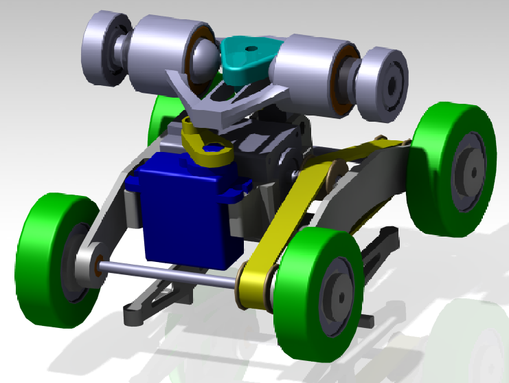 |
| Bogie Model 4 |
The model 4 is the most completed 2 floor bogie design. With the belt polley transmission from the central motor to the two drive wheels axis.
 |
| Bogie Model 4 |
This picture on the right side show the switch mecanism, using a cam roller to expand and springs (not shown one the CAD) to take back the wheels.
Then Jacques-Hariel worked on the track and redesigned the switch area for the 2 floors concept.
 |
| 2 floor guideway - switch area |
As already said, this guideway is built with the same beams than the current one but on the horizontally. This allow to cut the curved area with water jet and give more area for the wheels contact. The two supports (each side on the track) for the switch are water jet and welding with and L shape on the top (to lead the wheels). The two supports between the top and down floor are also water jet. The assembly use screw (M3 or M4).
 |
| Bogie on track |
On the left picture, we can see the bogie on the track. Of course it doesn't appear yet but we can imagine the podcar bellow the podcar.
 |
| Bogie on track |
This last picture give an idea of the switching process and alignement of the top wheels.
There is 4 points to observe :
- As already said the podcar must be less width than the inside track
- When the switching system is retracted is must be less width than the inside track to go downstair (some not yet done one this model)
- The bottum parts of the bogie (under the guideway) when we need to go straight. On a full scale system, these parts can be operated and turned inside at this time. On the 1/12th we can just add a flap on the track.
- The attachement of the springs
---
Small Scale Work: Single Support Axle System
This week, Ethan focused on finishing the track. This meant completing the switch, addressing the issue of joining acrylic parts (since the joint splines are designed to be .25" while acrylic is 4.5mm) and adjusting the width of the slider arms on the bogie.
Switch:
The switch is for all practical purposes completed. (A few pin holes need to be added for ease of assembly)


 The top and bottom plates are separated by some spacers (left). All parts are designed to be cut on the laser cutter or water jet, then glued together (Acrylic cement or even superglue). The spacers utilize a square peg style joinery. Peg size is finalized once the stock thickness is known.
A set of guide rails hang down from the top plate. They are just flat strips of material, held in place by the slots in the top part. Once the guides are bonded to the top plate, the whole top assembly should be extremely rigid, despite the slots for the strips running all the way down the top plate.
The overall construction is similar to the curve section in that a series of layers of plate material are used to build the structure.
---
Curve:
The curve was mostly completed last week. However, the method of joining the curve to the rest of the track was still of questionable quality. After designing the switch, Ethan modified the curve to reflect the joinery style used on the switch.

This is the end of the curve. We can see that the square holes that, on aluminum parts, go all the way through now stop a 16th inch from the end. This allows the square profile to be formed from a solid piece (if hole went all the way through, the pieces of acrylic between the holes would separate). With adhesive, the thin sections that form the hole should be strong enough. Unfortunately, this means that a taper fit is not possible for the joining of acrylic sections. I propose we use a little bit of hot glue or superglue, then heat the parts slightly to release the glue bond for disassembly. If anyone has a better idea, please let us know.
For reference, here is the new joint spline designed to be compatible with this and the standard aluminum joints:

It is basically the same, except the joining nubs are shorter.
---
Odds and Ends
In addition to the curve and switch, Ethan cadded the four inch straight section and the 16" and 32" straight assemblies.

Four inch section (Used when a switch is added)

16 inch section
The 32 inch section looks the same, just with two rings.
Yay!
And with the joining sorted out and all fundamental parts done, the track can be assembled!
A hint...

And another hint...

And there's the switch! (I haven't added the joint splines)

And here is my short layout:

Close up of the other switch:

And here is the bogie about to traverse the switch. Note the position of the slider:

Top View:

---
There are just a few more little things for this small scale:
- Get servo motor so slider can be finished
- Then finish slider
- Get acrylic and update cad for acrylic thickness
- Make tops of base towers interchangeable (to increase support areas)
---
Anything else?
Ethan created a design for an active/passive switching roller coaster design. It uses two bi stable lever arms with wheels on the end. The levers can be actuated by the track, or by a system on the bogie. Ethan will try to flush it out a bit more next week.

Commentaires
Enregistrer un commentaire