Third Week | 7/8/2019 - 7/12/2019: Refining Designs
Meeting Synopsis
We started this week with the monday 10am meeting with Ethan and Jacques-Hariel at the
Superway local, Ron and Eric on Skype. We discussed about the last designs :Two floors
guideway system of Jacques-Hariel and the Single drive pair of Ethan.
On the first one, Eric recommend to improve it by making it symmetrical for a better
distribution of the weight and a better stability; Maybe using 4 wheels rather than only 2 on
one side.

Eric’s draft
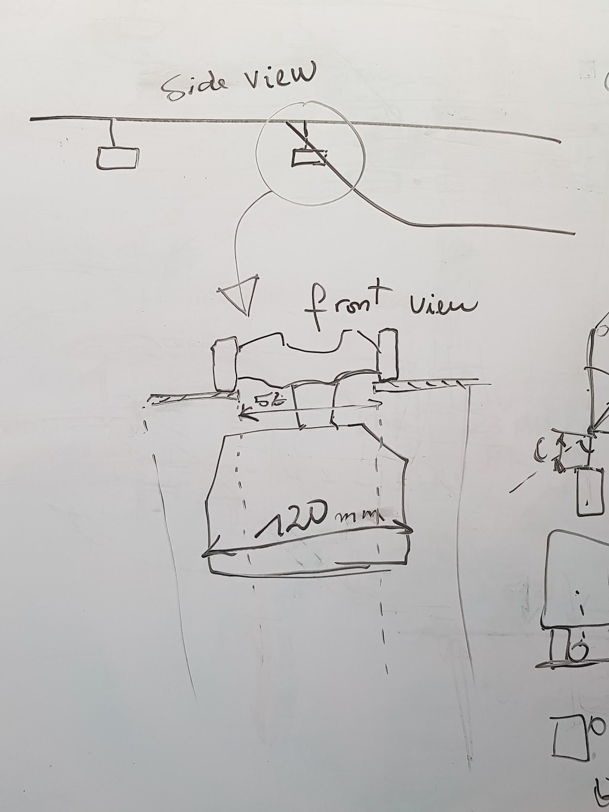
We also got a concern about the guideway system impacting the width of the podcar and
some collision with the bottom part of the bogie when the podcar goes straight.
Problem illustration
The evening we got a meeting with the Alumini at the local, Ron and Daniel on video
call. We discussed again about the last designs and manufacturing aspect.
We got constructive critics about the solutions from Daniel and sereval ways to improve.
Daniel concluded on considering the two floors guideway in prior with the single drive pair
and see how to match their advantages.
Design Synopsis
So far, we have three feasible designs: The two floor system, the single drive wheel slider and
the roller coaster. The following table better illustrates those such designs.


Design Progress
Two Floor Bogie:
Regarding Eric’s recommendation, Jacques worked this week on the bogie and came up with
a first improvement, as shown below :

Unfinished Bogie 2
On this bogie, the idea was to use a solenoid (in black) to activate a string transmission.
Using springs to come back on the open position and the traction of the solenoid to retract
the wheels.
After some other research (data sheet of solenoid), Jacques-Hariel realize that it might be
very difficult to have enough travel with the solenoid to retract the wheels.
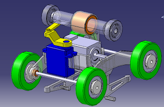
Then he decided to go on using a servo (proposed by Ethan earlier). On this second
improvement, He use only two symmetrical wheels at the top (should be enough) but the
system can be easily adapted for using four wheels at the top, for the switch. This design also
contains two blockers at the bottom to keep the bogie on the track and for lateral blockers
(two on each side) to keep the bogie on the right direction. The servo in blue can engage or
disengage the wheels for the switch.
Unfinished Bogie 3
Single Axle Slider:
Most of the development of this idea was on the guideway end. A curve guideway section
was designed utilizing layers of laser cut or water jet material (acrylic, polycarb, or
aluminum). This layered construction is intended to allow a very precise curve to be
manufactured from sheet type material.


One issue is that acrylic and polycarbonate sheet is not exactly fraction dimensions (ex. “.25”
inch sheet is actually .177”) There is a way to construct the curve with an aluminum
“backer” rail that holds a more flexible material in a permanently bent position. The flexible
material would act as the rail and contain the proper joint holes, while the aluminum backer
would enable the curve to be precisely controlled.
A switch is also in the process of being CADded.
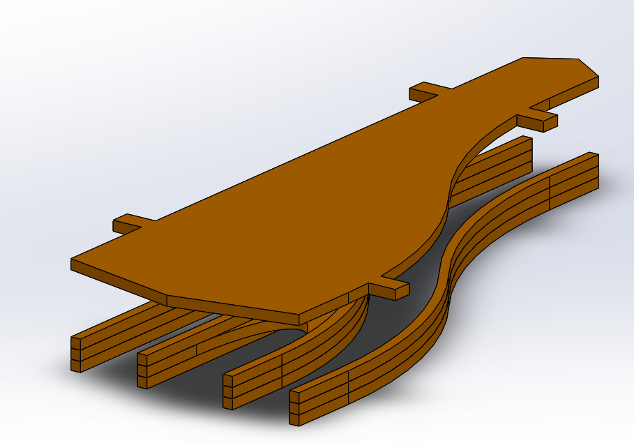

The guide rails will be attached to the big plate on top with tab and slot joinery. The bottom
sections will be attached to the top with acrylic “risers” cemented in place. Those risers
attach to the tabs on the top. The whole assembly is designed to be laser cut out of acrylic.
The rails are designed such that the outer curved section is tangent to the beginning and end
straight sections. The inner curve is concentric to the outer section.
In order to cad these components, the sizes of each section of track had to be calculated to
ensure that the system is modular. The base unit of the system is 16”, but 4” and 8” sections
are needed to integrate the switch assemblies. In addition, connecting rings and stands
can attach every 16” on straight sections. The following table contains these sizes.

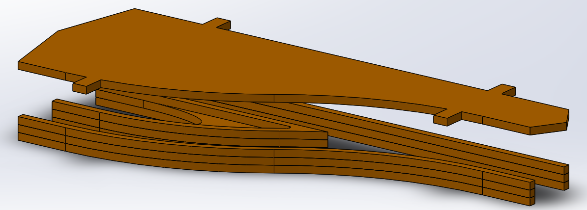
This is what a straight and curved setup might look like:

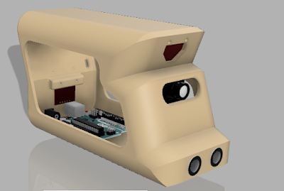
And here is the bogie just to remind you what it looks like:

Roller Coaster:
This is the least developed idea, but I think if flushed out, this may offer the greatest
potential for success. This week the idea was conceived... “What if we design the system, not
like a big monorail, but like a roller coaster. Since, out pods are probably closer in size to
roller coaster pods, not full monorails.” That intriguing thought led to some brainstorming
of how the switch would work, and how the rail would be constructed, etc.
If we did pursue this, it would have two round rails vertically separated with a two roller
coaster style trucks clamping onto the rail. It’s like the old old full scale system, but more
robust. zIt is also quite similar to the concept art in the first chart (which might help you
visualise the system). There are also currently no other projects currently pursuing this
design (unlike all the other designs). This either means that the design is bad, or that we
may have a competitive edge if we pursue it.
That about sums up this week! We probably won’t pursue the roller coaster design for our
small scale project (too new and hard to build at small scale), but we think that it may be
worth pursuing at the half or full scale during the next school year. The concept has the
potential to eliminate the gap issue, reduce track cost, make shifting grade to the station
easier, and perhaps integrate into existing infrastructure.

Commentaires
Enregistrer un commentaire